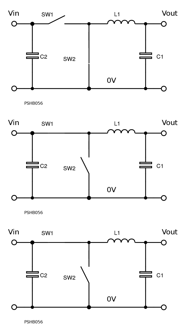
Used for: Stepping a voltage down in value with high efficiency
Pros:
- Simple step-
down circuit - High level of support with control ICs and application info
- Switch SW1 voltage limited to Vin + SW2 drop + spike
- Current limiting/short circuit protection relatively easy because of series switch
- Low output ripple current into C1
Cons:
- Needs high-
side gate drive or P- channel switch for SW1 - Step-
down in voltage only - High input ripple current from input cap C2 -
needs to be low ESR

Basics:
- SW1 and SW2 are alternately on and off at high frequency
- SW1 and SW2 are never both on together
Vout = Vin x D where D is the switching duty cycle (0 -1) - Input ripple current is high and must be sourced from C2
- Output ripple current into C1 can be low, set by L1 value
- SW2 can be a diode -
the action of SW1 turning off automatically forward biases the diode causing it to conduct. Action of SW1 turning on reverse biases the diode causing it to block current
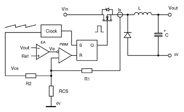
CONTROLLING A BUCK CONVERTER WITH CURRENT MODE CONTROL WITH SLOPE COMPENSATION

Vout is compared with a reference using the error amplifier producing a voltage Ve proportional to the difference. This is compared with a representation of inductor current Is as a voltage dropped across RCS. R2 adds in a small sawtooth signal to achieve slope compensation. Inductor current is a sawtooth so the PWM stage compares this with Ve to produce pulses: wider = output too low, narrower = output too high. See HERE for detail of PWM.
See HERE for explanation of slope compensation. Details such as error amplifer compensation have been omitted. See below
CONTROL LOOP PARAMETERS

Vramp = amplitude of sawtooth ramp from inductor current and slope compensation
Ri = Rcs = Rsense x Current gain eg. Rsense x 100 for 100:1 sense transformer
Optimum slope compensation assumed in each case
D = Duty cycle
f = operating frequency