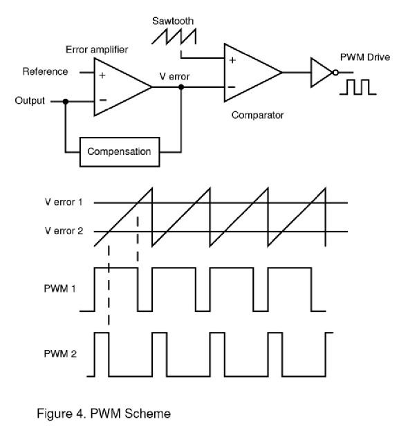
The target output voltage is compared with a fixed reference voltage in an error amplifier which produces an output Verror proportional to the error. This is compared with a sawtooth generated from a clock in voltage mode control or generated from output inductor current in current mode control. Sawtooth and Verror are then input to a comparator to produce pulses.
The lower part of the diagram shows the two pulse widths corresponding to two error voltages. If the sawtooth is lower than Verror the comparator has a low output. When the sawtooth becomes higher than Verror, it has a high output. Wide pulses to the main switch allow more energy through pushing the output voltage higher. Narrow pulses reduce energy and output voltage. Polarities are arranged so that if the output is too low Verror goes higher producing wider pulses and correcting the output error.