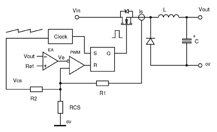
The diagram represents a buck converter in current mode control -
A particular instability occurs when converters, either boost or buck derived, are operating in continuous conduction mode above 50% duty cycle. This ‘subharmonic instability’ is fixed by adding some extra slope to the sensed current waveform, normally a sawtooth, which is acting to set the duty cycle. The extra slope is often easily obtained from the IC clock signal and is added in with R2 in the diagram. This technique of so called ‘slope compensation’ also has other benefits of improving response to input voltage changes so is always useful to implement even if the duty cycle is kept below 50%.