My recent post on ‘Quora’ on flyback magnetics and gaps:
Air gaps in flyback ‘transformers’
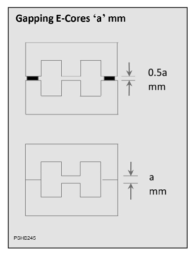
Why do flyback transformers need a gap in their cores? First let’s think why we need a core in a flyback converter in the first place: mainly to constrain the magnetic field inside the core to stop it coupling with other components causing losses and reduced coupling to the intended secondary coil. (forward converters are different). Let’s look at an example to show how it can work without a core, ignoring leakage field. Take a 10V supply, 20W output power P (ignore efficiency), 100kHz operating frequency (10µs cycle time T, 5µs on-time t). The average input current for 20W, 10V must be 2A. In the 5µs on-time this must average 4A. For a flyback in discontinuous mode (another topic) the current ramps from zero linearly to a peak which is twice the average in the on-time = 8A. Inductance L = Et/i so L = 6.25µH. You can get the same figure by equating energy in each switching cycle P x T with stored energy in an inductor 0.5 Li^2
From the ‘solenoid’ equation in air (µr =1), L= µr µ0 n^2 Area x 1000/length, this can be formed from an air coil 20mm long, 20mm diameter and 18 turns. Quite reasonable size for a 20W transformer with no core! The leakage field is the big problem though so a ferrite core is used to constrain it. Ferrite has much higher permeability µr (magnetic conductance) than air, maybe 2000x, so from the solenoid equation, inductance goes up in proportion to 12.5mH assuming the core area is the same as the coil area. We need to get back to 6.25µH so we leave the core in and reduce the turns. If we left the inductance at 12.5mH, the current would not have time to ramp to 8A in the on-time and the converter would be power-limited. Now from the solenoid equation for a continuous ferrite core with µr = 2000 we want 0.28 turns – obviously not practical. For say 6 turns we would need the effective permeability to be much lower which we can achieve with a gap in the magnetic circuit. Because the gap has a far higher magnetic resistance (reluctance) than the ferrite, the ferrite and gap in series are dominated by the value for the gap so we can use the gap length in our solenoid equation, giving gap = l = 2.27mm, This can be placed anywhere in the magnetic circuit but if it is in the middle of the coil, any stray field from the gap is shielded by the coil. We now have our inductance back, 6 turns which is workable and a ferrite core constraining the magnetic field with a workable 2.27mm gap. As a check we need to look at the flux density B in the ferrite which should not exceed the saturation value of about 0.4 teslas. B = L x ipeak/(area x turns) = 0.026 teslas which is fine. In an air coil, saturation is not possible. I have assumed the same coil dimensions all the way through but of course you can play with coil diameter and hence coil/core area to optimise further. For some designs it works, but current might be too high for the wire gauge/turns that will physically fit so you would need to iterate towards an optimum.
Given an existing inductor, introducing a gap and adjusting turns to get the inductance you want can reduce flux density and prevent saturation especially if there is a DC current component but this is not the usual starting point.
Note - in the equations inductance is in µH, length in mm, area in mm^2 and µ0 = 4 pi 10^-7, µr for air = 1
